In testing I’ve seen DB 0x47 give a 78% duty cycle, and DB 0x58 give a 48% duty cycle. I haven’t figured out the relationship from just that data so was hoping to get some more information here.
I am a little confused on your statement as you mention the DB command twice.
For Zigbee enabled devices, the DB value is going to give you the receive signal strength of the last packet received in Hex value.
Sorry I should have been clearer. I’m referring to the RSSI PWM output that can be enabled on Pin 7 of the XBee 3, and how this PWM value relates to the actual DB value.
I’ve found this documentation for the XBee S2C, which has the sort of thing I’m looking for: https://www.digi.com/resources/documentation/Digidocs/90002002/Concepts/c_zb_rssi_pwm.htm
I’m trying to find that same equation of “PWM counts = (A * RSSI_Unsigned) - B” for the XBee 3.
https://www.digi.com/resources/documentation/digidocs/90001539/#reference/r_cmd_rp.htm?Highlight=PWM
Hello.
I am looking for the same equation as @luca_fusion asked for. I read a lot of user guides and couldn’t find anything. Can anyone help me calculate the RSSI based on the PWM duration value, for an XBee 3 Pro (XB3-24Z8ST)?
I would suggest looking at the following:
https://www.digi.com/support/knowledge-base/pwm-rssi-signal-atrp-command-for-analog-rssi-indic
https://www.digi.com/support/knowledge-base/converting-the-xbee-pwm-to-an-analog-voltage-for-d
Keep in mind that the value is based on a Duty cycle. If your Duty cycle is .1sec, and you have the PWM on 50% of the time, that would put the RSSI at the center of the re-portable value.
@mvut , thank you for your reply.
I don’t need to convert the PWM signal to an analog one. I am using an Arduino board to read the PWM duration value and I need to calculate the RSSI. Those links are not helping me, or I do not understand their content properly. Can you be more specific, like give an example?
Thanks.
@Valentin I would suggest looking at page 59 at https://hub.digi.com/dp/path=/support/asset/xtend-vb-pkg-rs232-485-user-guide/
@mvut I looked at the info, but it does not seem right. First, it is for another module type. Then it is written that the total time period of the PWM output is 8.32 ms, and the PWM output consists of 40 steps, which does not apply to my XBee 3 module. I have the Digi XBee® 3 ZigBee® User Guide, Rev. N, and at page 279 it is mentioned that the PWM period is 64 μs and there are 0x03FF (1023 decimal) steps within this period. I also measured the signal with an oscilloscope and the period is indeed 64 μs.
Digi does not have a document that covers the exact product and protocol for what you want. You can figure it out as follows:
You divide the total number of steps with the PWM timer. Then break that up starting at the lowest RSSI possible for the module in question. That would be -103dBm. For each period of the PWM that is high indicates a value of the signal.
It is strange that Digi encoded the value of the RSSI in a PWM signal, but then is not offering a way to decode it.
As for your solution, it does not sound very precise. I will try, possibly with reading the RSSI value in API mode, and at the same time reading the timing of the PWM signal, and maybe I can find a correlation formula.
Thank you, @mvut !
I’m also very interested to find an “official” conversion formula from RSSI PWM duty to -dBm reception strength.
Has anyone here found this information?
Please see my post from Aug of 2024. Please remember that the PWM is user settable. It is not something that Digi can provide on a user settable function.
(from Xbee3 User Guide)
“When configured as RSSI PWM output, the device outputs a PWM signal with a duty cycle equivalent to the dBm of the received packet.”
So i understand PWM duty on this pin is not settable when you use it as RSSI PWM output.
I really don’t understand why Digi is offering a RSSI PWM out without giving the probably simple formula to convert it’s duty to dBm…
Also see The PWM period is 64 µs and there are 0x03FF (1023 decimal) steps within this period. When M0 = 0 (0% PWM), 0x01FF (50% PWM), 0x03FF (100% PWM), and so forth. 100% PWM is a full strength packet.
Thanks, I read that too, but it doesn’t give the relationship between the PWM duty cycle and the reception level.
The information I am looking for was for example available for old Xbee modules in the following form:
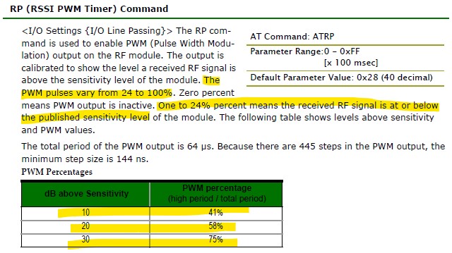
This function is the exact same as it was before. That is, if you are using the Xbee 3 Zigbee, 802.15.4 or Digi Mesh modules, it is the same as it was with the original XBee modules with the same protocol.