How can I get these xbees to work?

I am following the instructions given in this pdf, http://cytron.com.my/attachment/Details%20Description/PR20_DD.pdf (just the programming on page 7, not the PCB, just breadboarded it.)

The following settings were used:

(This was done in the modem configuration tab, not the terminal)

Input:

ATDL1111
ATMY2222
ATD02
ATD12
ATD23
ATD33
ATD43
ATD53
ATD63
ATD73
ATIR0F
ATIT0F
ATWR

Output:

ATMY1111
ATIA2222
ATD15 (I’m assuming a typo in the instructions which said ATD25 twice)
ATD35
ATD45
ATD55
ATD65
ATD75
ATWR

I have all the inputs connected to 3.3V, so what I want to see is all the LEDs at the output lit up. However, they do not. I have verified that the LEDs work, and I’ve tried two different resistor values with the LEDs (550 and 10k).

Maybe someone can please tell me if these AT commands should work or not? Or what is wrong with my setup?

I also went down the checklist of common xbee mistakes at http://www.faludi.com/projects/common-xbee-mistakes/

Not using the latest firmware (especially if ATD0 or ATIR is giving an error)*

-The first thing I did was update the firmware to 10E6.

No reference voltage to VREF pin on the 802.15.4 radios (analog and digital reads give wrong values)

-I put 3.3V on VREF pin. Even a wrong value would be better than seeing nothing, though.

Forgetting that AT commands use hexadecimals

-All my AT commands are using values less than 10 anyway

Hitting return after +++ (or otherwise not respecting 1 second default guard time)

Conversely, not hitting return after an AT command

Letting the XBee time out of command mode before issuing an AT command (you’ll know because you get no response)

Forgetting to write the configuration to firmware with ATWR (unless your application configures the radio interactively)

-These four are not applicable because I was not using the terminal. I was using the Modem Configuration tab on X-CTU. I know the settings were saved because they are still read even after power to the xbee was disconnected.

Not using ATRE (restore factory defaults) before re-configuring a previously used radio (previous settings lurk unless you manually reset them all)

Not applicable because xbees were bought new (but I did this anyway)

Looking for analog output on the analog input pins instead of pins 6 and 7 (P0, P1)

-I’m looking for output everywhere. I’ve got LEDs on pins 11, 12, 15, 16, 17, 18, 19, 20, and there’s one LED that I’m moving around to check pins 2,3,and 7. LEDs are lighting up on pins 11, 12, 15, and 16, but they remain lit even if the corresponding inputs are put low. So this output is still not satisfactory. I want the output to respond to changes in input.

Using a voltage regulator without decoupling capacitors (10uF on input, 1uF on output is good)

-Not using a regulator right now because I’m testing the xbees in isolation, so 3.3V is being put in directly from the power supply.

Mixing up TX and RX pins (fastest way to check this is switch the wires and see if it starts working)

-I think this is only if we’re using a microcontroller. While I will eventually want to do this, right now I just want to see the output xbee change with the input xbee, i.e. I just want to see them working.

Using ZigBee version (ZB Pro or ZNet 2.5) when 802.15.4 version would do just fine (if you don’t need to make a mesh network)

Trying to read more than 1.2 Volts on the ZB Pro and ZNet 2.5 analog inputs (that’s the limit)

Buying Pro radios when you don’t need them. (Cost more, bigger, use a lot more battery)

-These 3 are not applicable

Deciding the XBees are flaky. (You may not be using them correctly, but they are very reliable)

-I’m still trying

Deciding an XBee is burned out when it’s set to a different baud rate (check ON and ASSC lights)

Deciding an XBee is burned out when it is just sleeping (Check ON light to see if it blinks occasionally)

-For these two, I have a different breakout board that doesn’t have these lights, they are set to the same baudrate, and I don’t think they are burned out because they are new. I couldn’t have gotten two bad ones, could I?

Forgetting to supply power or ground (ON light may go on and ASSC light may blink but both will be significantly dimmer)

-I’m fairly certain I supplied power and ground. Again, I lack these lights but I checked with a voltmeter.

Not contacting Digi sooner for support, especially if your radio seems dead or you keep getting an error you don’t understand.

-I may well have to do this. I tried running the range test and for both the radios it just says “Timeout waiting for data” even though the modem configuration tab is able to read the AT commands. But like I said, what are the odds of getting 2 new xbees and both of them are bad?

I’ve attached a picture of the setup. Input is on the left, output is on the right. The four rightmost LEDs (on pins 16,15,12,and 11) are lit. But 16 and 11 are lit very dimly so they don’t show up in the picture.

In addition, the RESET’ pin is pulled high, because it’s active low if I’m interpreting the notation correctly.

I have also tried the code “XBee Direct I/O with ADC” http://www.faludi.com/2006/12/03/xbee-direct-io-with-adc/

Getting the same result as previously described with the other code. If it helps, each of the lit LEDs has 2.3V on it (the brightly lit ones as well as the dimly lit ones). Any recommendations?

Are the xbee’s associated? Check the Associate Led output, if they don’t associate, try ATAI to get the error code, that might help find out why they aren’t communicating.

Regards
Ray

Hi, thanks for your response. Right now I’m using different code that at least gets some kind of response, whereas the original code produced no lights.

I think the associate output is pin 15, on the receiver that LED is blinking (see video), and the LED on pin 11 (DIO4) is glowing dimly. It does this whether or not the transmitter is powered. As for ATAI, someone hinted that I should set the association indicator as 0. (He didn’t say this specifically but he didn’t correct me either.)

This blinking output is not what I want, by the way. Shouldn’t all the output LEDs be lit if all inputs to the transmitter are high?

Right now I’m using different code, someone told me the following:

Access serial port with XCTU.
Confirm firmware type and version number. Make note of these. tell us.
Reset to factory defaults.
config. node type as FFD/router, not coordinator. Both units.
config. association required = false, both units.
In unit A, enter the MAC address in DL and DH for unit B. Vice-versa for unit A.
save settings.

So here’s what I tried:

On “NI- Node Identifier” I put ROUTER
(the default is just blank)

AI - Association Indication is 0
A2 - Coordinator Association is 0
A1 - End Device Association is 0 (these were default values)

Same MAC address for input and output: DA=1 and DL=2.

XCTU keeps saying the modem’s firmware isn’t updated even though I just did it.

What I’m trying to do is called “virtual wire.” (Yes these are Series 1.) So basically the xbees would be a serial wire replacement. There are other approaches I’ve been meaning to try, I’ll get back to you. Or if you know something that works, I’d appreciate any suggestion. Thanks again

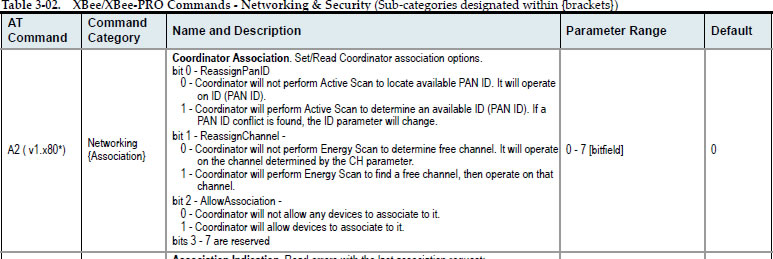
Here are the a1 and a2 parameters for Series 1 XBEE

The a1 parameter controls the end-device association (the one with atce 0)

If set using “ata1 7” should associate with anything… :slight_smile:

The a2 parameter controls the coordinator association (the one with atce 1)
If set with “ata2 7” it will scan and associate with anything

The atai ( note the “i” not “one” ) reports back the associate status
if you are getting “0” in response to “atai” then you’ve already associated.

Regards
Ray

PS… I should have asked, is one of the devices set as coordinator?

PS… I should have asked, is one of the devices set as coordinator?

No, I was told to set both as routers. Does it matter which one is the end device and which is the coordinator?

if you are getting “0” in response to “atai” then you’ve already associated.

I set it as 0 though. It may or may not be associated but the outputs are not right.

Let me try setting a1 and a2 as 7.

[quote]PS… I should have asked, is one of the devices set as coordinator?

No, I was told to set both as routers. Does it matter which one is the end device and which is the coordinator?

Let me try setting a1 and a2 as 7.[/quote]

Hmmm… there are multiple ways this can work, I suspect however the advice you have been given is relevant to Series 2 XBEE’s I’m still unravelling the differences between series 1 and series 2…

There is a beacon mode, but I’ve never used it. I always have a coordinator device… The series 1 can be set to act as a coordinator using “atce 1” or as an endpoint using “atce 0”

Regards
Ray

By the way, I set them through the modem configuration tab, not the terminal, same thing right?

I set the transmitter as the end device (atce 0, ata1 7) and the receiver as the coordinator (atce 1, ata2 7) but I am getting the same response from the pins. It might be my imagination but the blink rate seems to be slower. (See video)

Was I supposed to revert to factory defaults before applying these settings?

[quote]if you are getting “0” in response to “atai” then you’ve already associated.

I set it as 0 though. It may or may not be associated but the outputs are not right.

Let me try setting a1 and a2 as 7.[/quote]

Ahh… are you sending “atai 0” perhaps, the “atai” command is for QUERYING the association status, just send “atai” and see what comes back.

Regards
Ray

I suspect however the advice you have been given is relevant to Series 2 XBEE’s I’m still unravelling the differences between series 1 and series 2…

Series 1 is supposed to be a lot easier to do virtual wire with. Series 2 is for mesh networks. There’s also Series 2.5 - ?

The series 1 can be set to act as a coordinator using “atce 1” or as an endpoint using “atce 0”

I’ve tried that, see my 7:00:26 post

what does “atai” return?

If it’s zero then, you should have a serial connection from end to end

Regards
Ray

I’ve tried that, see my 7:00:26 post

Not sure what that means, I suspect you are referring to the time, but I’m on GMT+10 timezone…

What did “atai” return?

Regards
Ray

Not sure what that means, I suspect you are referring to the time

I’m referring to the time given at the bottom of the post.

just send “atai” and see what comes back.

I already told you it returns 0, in fact I’ve never seen it anything but 0.
But am I supposed to be sending queries with both xbees on? For that, I think I’d have to try the wireless serial port mode
(XCTU terminal mode on unit A. Confirm keys pressed appear at unit B’s serial port output) But I’m not sure how to do that, so I’ll have to play with it.

[quote]Not sure what that means, I suspect you are referring to the time

I’m referring to the time given at the bottom of the post.
[/quote]
That’s what I suspected, but it might interest you to know, that the time displayed on YOUR pc is offset by whatever timezone you happen to be in. Since you and I are in different time zones, the time you see is different to me. Telling me the time doesn’t help.

[quote]just send “atai” and see what comes back.

I already told you it returns 0, in fact I’ve never seen it anything but 0.
[/quote]
Well, actually no, you said (twice) that you had SET it to zero, not the same as reading a response of zero.
Anyway, if you get “0” in response to “atai” then you are connected. Whatever else you might wish to do is related to reading the analog/digital io and your hardware.

But am I supposed to be sending queries with both xbees on? For that, I think I’d have to try the wireless serial port mode
(XCTU terminal mode on unit A. Confirm keys pressed appear at unit B’s serial port output) But I’m not sure how to do that, so I’ll have to play with it.

Or, get another pc running a dumb terminal program to watch the serial data at the other end. You will of course need to change from ttl levels to rs232, but I assume you know that.

Regards
Ray