I have I/O line passing working fine on a pair of Xbees (four i/o lines) after the fashion of this knowledge base article: http://www.digi.com/support/kbase/kbaseresultdetl.jsp?id=2188
but there’s a transmitter and a receiver. Is it possible to have the same thing, just bidirectional? So when an i/o pin on either Xbee experiences a change from 0->1 or 1->0, it will transmit it to the other one. Or, if the same i/o pin cannot be bidirectional, it would probably be possible to configure two DIO pins as input and two as output on the same Xbee, right? Definitely wouldn’t need 2 sets of Xbees.
I really only need two i/o lines.
Also, only digital data can be transmitted and received, right? Not analog? I know it has ADC, but if I went with analog I wouldn’t want the Xbees to convert it.
In summary, there are two possibilities for I/O line passing that would be of interest to me if anyone happens to know:
And you can also do analog line passing according to the product manual.
Thanks for the response. Are you talking about using an analog input to the AD0 pin to change a PWM value sent out pin PWM0 of the receiver? Presumably AD1 will control PWM1 as well, giving two lines of analog line passing, correct?
In the bidirectional digital case, I would have a situation like the one shown below:
(Note: for simplicity I didn’t show the Xbees, just the relevant pins. And also the two Xbees are on different boards.)
I’m not sure this would work though. Say if both sides were 3.3V, then one side got pulled to GND, would the change propagate to both sides, or would it be just 1.5V or something?
I guess I would need some kind of switch that would send it to one wire if the value was high, and send it to another wire if the value was low. But the switch should be automatic, it shouldn’t need to be manually adjusted.
I don’t think I can really help much further, because it’s not clear what you’re trying to achieve with this.
You appear to want to connect together two lines each of which can be driven high or low. Unless you’re trying to emulate some sort of open-collector circuit, surely that can’t work?
Dear Sir, Thank you for your interest. The application is a wireless PS/2 mouse. This is outside the scope of this forum, so instead of me posting the details here, please visit http://www.avrfreaks.net/index.php?name=PNphpBB2&file=viewtopic&t=103141&postdays=0&postorder=asc if you want to know the details. PS/2 uses an open-collector interface, there are two lines going out from the microcontroller: Data out and Clock out. This is why I would need two bidirectional I/O lines.
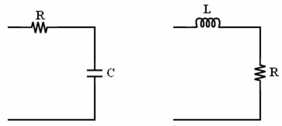
On second thought, I’m having trouble getting the device to work, even wired, so I might not want to pile wireless on top of that. I found some Digi articles showing how to use the ADCs as well as how to put filters at the other end to get an analog signal from the PWM. ADC inputs to the MCU must be <10Kohms, but the example circuit they provide is certainly below that. I have a question about their diagram however:
I would be using the RC version. Would the XBee output go to the left side of the R, then the other loose end would go to the microcontroller?
Unidirectional analog would be easier to test, even though it would be more costly in terms of Xbees.
I’ve mentioned my other pair before, it’s the one where one of them is “Maxstream” and the other one is “Digi International” and you informed me that they should work together with updated firmware. I’ll try it first with the unidirectional code, then with the new code. I’ll post a different thread if there are problems. What do you think?